ESP8266 with RFM69 using Lowpowerlab
UPDATE: interesting new git project: https://github.com/bbx10/nanohab I’ll want to try it out soon!
I stumbled upon two different communities working on incorporating RFM into an ESP8266 environment or vice versa: Mysensors.org and Lowpowerlab.
My previous post discussed pinout for mysensors library. But, given that the funky’s I’m using worked so well with the Lowpowerlab library, I decided to look at leveraging their library to be run on the ESP8266.
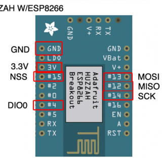
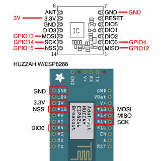
| Pin Name | ESP8266 GPIO # | ESP8266 HSPI Function | RFM69 Pin | Arduino |
|---|---|---|---|---|
| MTDI | GPIO12 | MISO (DIN) | MISO | 12 |
| MTCK | GPIO13 | MOSI (DOUT) | MOSI | 11 |
| MTMS | GPIO14 | CLOCK | SCK | 13 |
| MTDO | GPIO15 | CS / SS (Select Slave) | NSS | 10 |
| GPIO4 | IRQ (Interrupt) | DIO0 | 2 |
Rev A of the Huzzah ESP8266 board has GPIO #4 and #5 swapped (the modules changed pinouts on us)
- MISO (Master In Slave Out) – The Slave line for sending data to the master,
- MOSI (Master Out Slave In) – The Master line for sending data to the peripherals,
- SCK (Serial Clock) – The clock pulses which synchronize data transmission generated by the master
and one line specific for every device:
- SS (Slave Select) – the pin on each device that the master can use to enable and disable specific devices.


Per Joelucid
Then in RFM69.h:
#define RF69_IRQ_PIN          4
#define RF69_IRQ_NUM          4
Then from the lowerPowerLab sketch change CS to 15
radio.setCS(15);
https://lowpowerlab.com/forum/index.php/topic,1389.0.html
”
To make matters more interesting, I’m using Martin’s Funky V3 with my RFM69.
In his version of the LowPowerLab’s Struct_Receive/Send, he sets the CS Pin to 10. I’ll try changing that to 15 in the ESP code to see if it works.


